2012-08-29
An essential feature of the quality of single frequency networks is the time synchronisation of the transmitters. The same COFDM signal is emitted by all the transmitters at the same time — except for a time lag of a few microseconds sometimes intentionally inserted for reasons of fine-tuning.
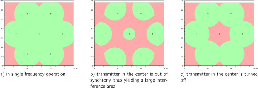
Figure 1: Service areas of a single frequency network consisting of seven transmitters in different operation states. The respectively covered area is printed in green.
Figure 1 illustrates what happens if this synchronisation condition is not met. It shows the service area of a single frequency network consisting of seven transmitters, computed with a simplified propagation model. The service area in the case of a synchronisation failure (b) is smaller than that resulting from the failure of the transmitter in the center (c). It is therefore absolutely necessary to react promptly to a synchronisation failure.
In order to compensate varying delays during the transmission of the signal from head end to the transmitter locations, a dynamic delay compensation is generally applied today with time stamps inserted into the ETI signal. In such a DAB single frequency network, the time position of the emitted COFDM signal is determined; time marks in the transmitted DAB signal, such as the periodically occurring Null Symbol, occur at the same, reproducible time at all the transmitters in the single frequency network.
The principle of synchronisation monitoring applied for the SDMB 100 and the DAB-XPlorer with UEB400-DXP receiver takes advantage of this fact in order to detect synchronisation failures. Both devices continuously monitor the time of transmission of a particular Null Symbol with respect to a standard time. Whilst the UEB400-DXP uses its integrated GPS receiver as time standard, the SDMB 100 relies on an external 1 PPS clock in combination with the time delivered by an NTP server. Optional an internal GPS receiver is avialable for the SDMB 100 as well.
Figure 2 shows which time marks within the DAB signal are used for synchronisation monitoring.
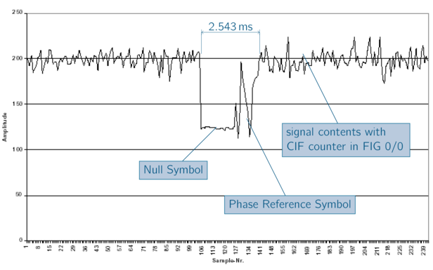
Figure 2: Time marks in the DAB signal in the time interval. The figure shows the first section of a transport frame of a length of 96 ms (mode I), with the synchronisation channel consisting of Null Symbol and Phase Reference Symbol. After the decoding of the FIC contents, the CIF counter from FIG 0/0 is also available.
At the start of each Null Symbol, the DAB receiver integrated in the monitoring device provides a periodic frame trigger signal; its time position can be correlated to the 1 PPS pulse given by the internal or external GPS receiver with an exactness of one microsecond by appropriate hardware.

Figure 3: Measurement principle of the time position of the Null Symbol during stationary on-site monitoring.
The CIF counter encoded in FIG 0/0 of the FIC counts the Common Interleaved Frames (CIF) modulo 5,000. A CIF has a length of 24 ms; a CIF counter 0 therefore occurs exactly every 120 seconds. With the help of the CIF counter from the decoded FIC, we can determine to which frame the frame trigger used for the determination of tn in figure 3 belongs. The time of the pulse per second used for the measurement is also known, either from the integrated GPS receiver or from NTP. Thus it is possible to compute the time of the start of the Null Symbol belonging to the frame with CIF counter 0. The time difference Δt between the 2-minutes limit of the standard time and the start of the Null Symbol of frame 0 is the value measured in microseconds by the monitoring device as the quality criterion for the synchronisation.

Figure 4: Definition of the delay as the time difference between the 2-minutes limit of the GPS time and the occurrence of the Phase Reference Symbol in the transmission frame, which includes a Common Interleaved Frame with the counter 0.
In the case of an error-free operation, the delay Δt must remain constant at a transmitter location during the entire runtime of the single frequency network (i.e. as long as the multiplexer is not shut down). If this value is also identical from transmitter to transmitter, we can speak of an ideal synchronisation of the network. The delay Δt, measured with a resolution of 1 microsecond, can have values from 0 to 119 999 999 µs.
The supervision of synchrony in DAB SFNs can either be made by analysing the channel impulse response or by measuring and comparing the temporal positions of all transmitted COFDM signals. This article describes the second of these two methods that is implemented as well in the SDMB 100 as in the UEB400-DXP test receiver that is part of the DAB-XPlorer family of products.